A microwave circuit load defines the impedance presented to a microwave network at operating frequency.
I have designed and tested RF links and microwave modules for years, and I write this to help engineers and hobbyists master the microwave circuit load. This article explains what a microwave circuit load is, why it matters, and how to measure, match, and protect it in real systems. Read on for practical tips, real-world lessons, and clear steps you can apply right away.

Understanding the microwave circuit load
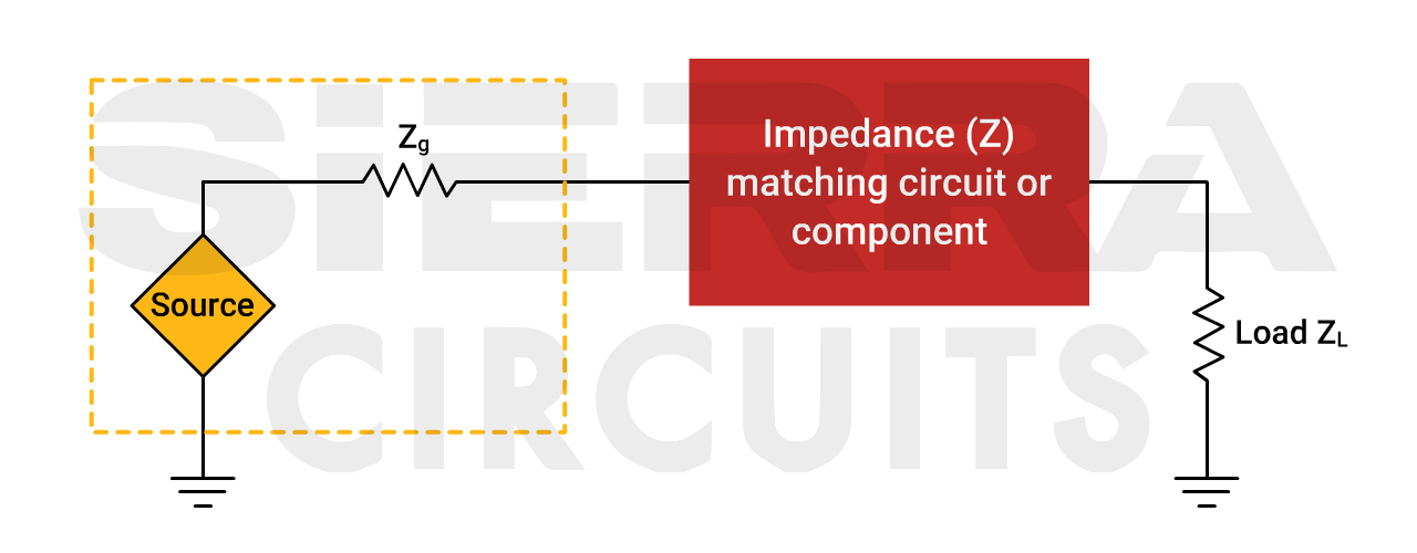
A microwave circuit load is the impedance that a microwave source sees at its output. It can be purely resistive, reactive, or a complex mix that varies with frequency. The load controls how much power transfers and how much reflects back toward the source. Managing the microwave circuit load is key for efficient power delivery, low distortion, and stable operation.
Types and characteristics of microwave circuit load
Loads at microwave frequencies take several forms. Each affects system behavior differently.
- Resistive load: Pure resistance over the band. This is ideal for maximum power transfer when matched to the source.
- Reactive load: Inductive or capacitive behavior. It stores and returns energy, creating phase shifts and standing waves.
- Complex load: Frequency-dependent mix of R and X. Typical in antennas, filters, and transistor outputs.
- Mismatched load: Any load not equal to the source conjugate. This causes reflections and possible instabilities.
Key parameters to watch for each microwave circuit load are impedance (Z), return loss, VSWR, and phase. These numbers tell you how well the load and source are matched. When designing, always plot impedance over the operating band. This highlights resonances and reactive swings.

Measurement and metrics for microwave circuit load
You must measure loads correctly to act on them. Use these standard metrics.
- S-parameters: S11 gives reflection at the port. S21 shows transmitted gain or loss.
- VSWR (Voltage Standing Wave Ratio): Measures mismatch. VSWR near 1 means good match.
- Return loss: Expressed in dB, shows how much power returns to the source. Higher is better.
- Smith chart: Visual tool to plot complex impedance and observe frequency behavior.
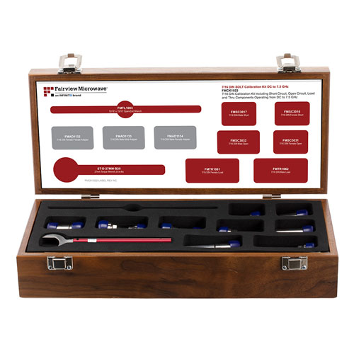
Use a calibrated vector network analyzer (VNA) to get accurate S11 and Z. When I started, I used an uncalibrated VNA and chased false resonances for days. Proper calibration saved time and gave confidence in load data. Record measurements at operating power when you can, since some loads shift with power and temperature.
Design and matching techniques for microwave circuit load
Matching the microwave circuit load to the source is essential. Here are common methods.
- Lumped matching: Use small capacitors and inductors for narrowband matching at lower microwave bands.
- Transmission line matching: Quarter-wave transformers and stubs work well at microwave frequencies.
- Tuners and networks: Mechanical tuners or adjustable networks allow real-time matching in test setups.
- Matching using simulation: EM and circuit simulators predict how a microwave circuit load will behave before hardware build.
Start by finding the conjugate of the load impedance on a Smith chart. Then design a network that moves the load point to the center. In practice, allow margin for manufacturing tolerances. My tip: prototype the matching network on a PCB and tune with small trimmers. This saved me several rounds of redesign when component parasitics changed the match.
Practical applications and case studies
Understanding microwave circuit load helps across many systems.
- Antenna feeding: Mismatches cause radiation loss and amplifier stress. Proper loading improves range and efficiency.
- Power amplifiers: The amplifier sees the microwave circuit load and can oscillate or distort if improperly matched.
- Filters and duplexers: These present frequency-dependent loads and must be designed with their load seen by the source in mind.
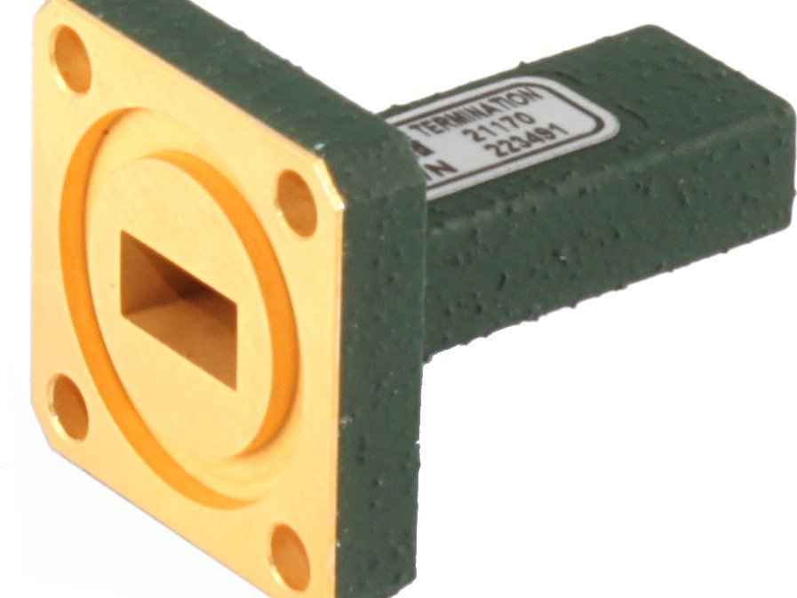
- Waveguide systems: Loads can be absorptive terminators or antennas. Waveguide loads behave differently than microstrip.
Case study: A small radar team I worked with had poor range due to a sloppy feed match. We measured the microwave circuit load and found a reactive dip near the band edge. A quarter-wave transformer fixed it and improved the system sensitivity by 3 dB. That step improved detection and reduced false alarms.
Troubleshooting and protection for microwave circuit load
Troubles happen. Here are steps to diagnose and harden systems.
- Check connections first: Loose connectors create parasitic reactance and intermittent mismatch.
- Measure S11 across the band: Look for dips and peaks that indicate resonance or damage.
- Test with a known load: Connect a calibrated 50-ohm load to isolate source issues from load issues.
- Add protection: Use isolators, circulators, or limiters to protect amplifiers from reflected power.
I once damaged an LNA by driving it into a bad load during tests. After that, I always used a directional coupler to monitor reflected power. That small change prevented repeat damage and made tests safer.
Best practices and practical tips
Simple steps reduce headaches and improve performance with microwave circuit load.
- Always document the measured impedance across the band for each device.
- Use high-quality connectors and short transitions to limit parasitic effects.
- Simulate before building, then validate with a VNA at full power when possible.
- Include margins for temperature shifts and manufacturing variance.
- Use shielding and good grounding to avoid stray coupling that alters the microwave circuit load.
These habits cut debug time and make results repeatable. In my lab, a checklist that includes cleaning connectors and calibrating the VNA saved hours and improved data consistency.
Frequently Asked Questions of microwave circuit load
What is the difference between a matched and mismatched microwave circuit load?
A matched microwave circuit load equals the source conjugate impedance, maximizing power transfer. A mismatched load reflects part of the power back, causing loss and possible instability.
How do I measure the microwave circuit load?
Use a calibrated vector network analyzer to measure S11 and convert to impedance on a Smith chart. Measure across the operating band and at realistic power levels for best results.
Can mismatched microwave circuit load damage components?
Yes. High reflections can raise standing wave ratios and stress amplifiers or cause oscillations. Use isolators or limiters to protect sensitive devices.
When should I use a tuner for microwave circuit load matching?
Use a tuner during prototyping or when the load varies in the field. Tuners are great for real-time adjustment but are not ideal for compact final products.
What is the role of the Smith chart with microwave circuit load?
The Smith chart visualizes complex impedance and helps design matching networks. It makes it easy to see how to move the load point to the desired match.
Conclusion
Managing the microwave circuit load is central to reliable, efficient microwave systems. Measure the load well, design robust matches, and protect active devices from reflections. Start by recording impedance, simulating options, and validating with a VNA. Implement these steps to reduce failures and improve performance. Try one improvement today—measure the load on a key link and see what tuning does to your system. Share your results, subscribe for more guides, or leave a comment with questions.